
Industrial grade rotary screw air compressors are typically driven by a 3-phase asynchronous electrical motor. These motors range from 5 kW to 1000 kW or more.
Because of the size of these motors, starting them up can result in a huge current surge, that can last for several seconds, or more.
For small air compressors (< 5 kW) this is not a problem - we can start them up directly using a so called "Direct Online" or DOL system.
For larger compressors, this current peak is way too high. This surge in current is the result of the 'virtual' overload condition the motor is under at startup.
We need to limit the currents, in order to prevent both the motor, the electric cabling and other various electric components in the electrical mains system of the compressor.
Startup systems used
Let's take a closer look at the different ways that are used in air compressors (and any industrial machine with electric motors). I will limit amount of theory about it and show you what this actually looks like in a real-life industrial air compressor.
There are different startup systems used:
- DOL (direct online)
- Star/delta (Y-D or Wye-Delta) starter
- Softstarter
- Frequency drive
DOL and Star-Delta starters use simple mechanical contactors (big relays) to start the motor. Softstarters and frequency drives use advanced mico-electronics to alter voltage and frequency during startup to greatly reduce the startup current. (think of a softstarter as a super simple frequency drive, only used during startup).
In this article I will shorty discuss the DOL method and spend the rest of the time on the Star-Delta method, since this method is used in 95% (if not more) of industrial air compressors.
DOL / Direct online
With DOL, or 'direct online', the motor is simply started up by closing a contactor. There is no special startup system in place.
This makes this method only suitable for small electric motors, typically below 5 kW.
 DOL system example in small compressor
The electric diagram is also pretty simple. It consists of a single contactor (a big relay, or electrically controlled switch) that is closed by a signal from the main controller. The startup current of the motor is around 7 to 9 times the nominal running current.
For example, a 4 kW motor has a nominal running current of around 7 amp. With a DOL startup, the current will peak around 50 - 60 amp.
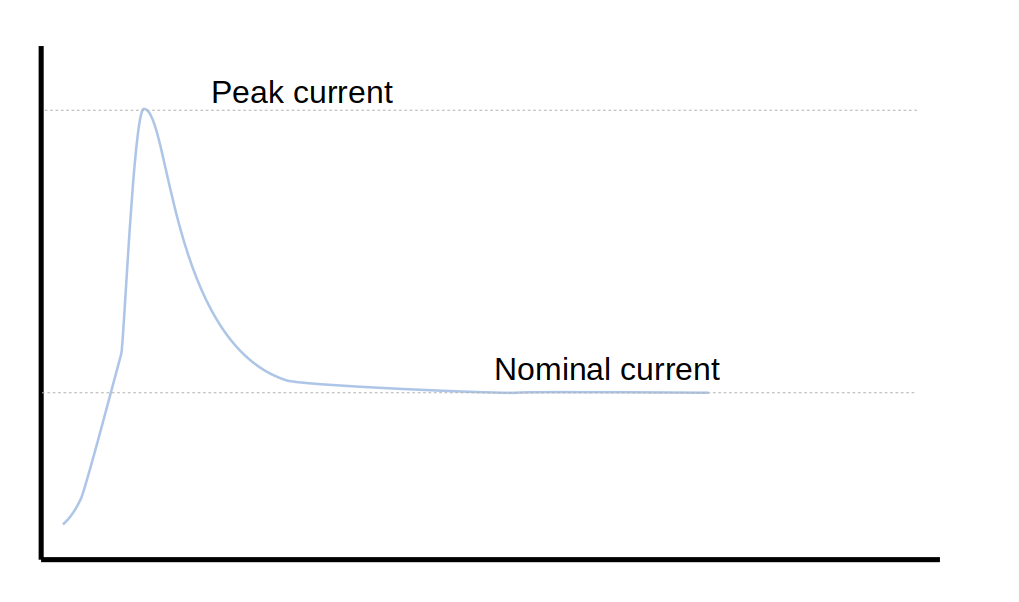 Startup current peak for a DOL system
3-phase electric motors
Before looking at the Star-Delta startup method, we first need to know a bit more about 3-phase industrial electric motors.
3-phase asynchronous motor convert electric energy into rotational energy using a rotating magnetic field. The magnetic field is created with the help of different motor windings, or coils. These windings are fixed/stationary at the outside part of the motor (the stator).
Because of the 'rotating' 3-phase power supply (3 phases offset at 120 degrees), a rotating magnetic field is created. The rotor rotates inside the stator, at a slightly lower speed (rpm) - that's why they are called 'asynchronous' motors. The difference between the speed of the rotor and that of the magnetic field is called the 'slip' and is usually a few percent.
These motors have 3 coils/windings and 6 connections (2 connections per coil). We can connect these coils in 2 different ways to a 3-phase electrical network:
- Star - we bundle 3 connections together and connect the remaining 3 connections to the 3 phases.
- Delta - we connect each coil between two phases - resulting in two connections per phase.
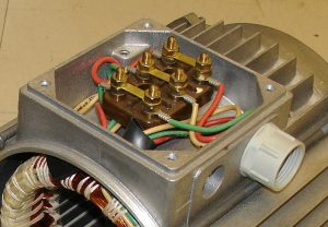 Connections terminals - this motor is connected in Delta
In the picture above you can see 6 wires/connections. Two are connected together by the interlink plates. In this example, the motor is hard-wired in a delta-configuration. The incoming 3-phase supply must be connected to each one of the pairs. If the motor was connected in a star-configuration, we would see the connecting plates all on one side, make a single star point.
Voltages
The difference between these two layouts is the voltage over each individual phase. The supply voltage in a typical industrial electric system is 400 volt (phase-to-phase).
In delta, the coils of the motor are directly connected between the phases, so they 'see' 400 volt.
In star - things are a bit more complicated: the phase-to-phase voltage (400 volt) is divided between two coils (and also passes through the center star connection) - the resulting voltage over each coil is 230 volt (400 volt / square root of 3).
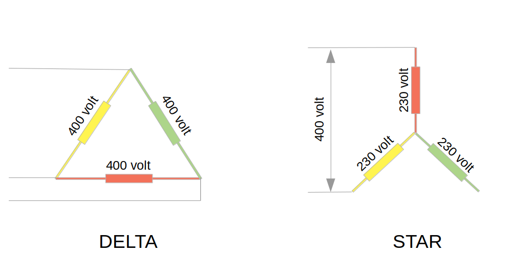 Delta and Star connections
This lower voltage per coil decreases the current (and the motor torque/power as well). The nameplate of industrial motors will tell you the nominal voltage when connected in delta and/or in star.
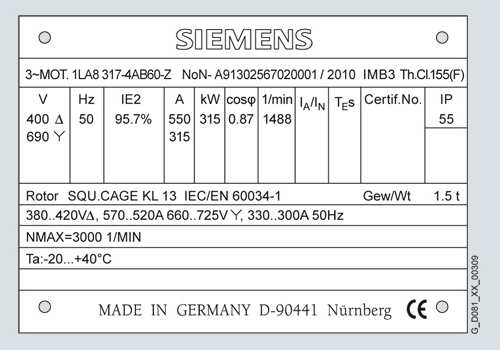 Electric motor nameplate example
The motor in this example is a 400/690 volt motor - if your electric system is 4400 volt, you should connect it in delta. If you have a 690 volt system - you should connect it in star. (note that the voltage over the winding is the same in both cases - in a star configuration, the voltage over the winding is 690 / sqr 3 = 400 volt).
Star / Delta
Back to the startup systems... Star/delta (Y-D) is the most common system deployed in air compressors, or in industrial machines in general. It's simple, easy to understand, easy to troubleshoot and doesn't require expensive electronics.
With Y-D starter we take advantage of the lower per-winding voltage when the motor is connected in star. So we use a motor that should normally run in delta, but start it up in a star configuration.
Remember, the motor in our example has a nominal voltage of 400 in delta and 690 in star. If we have a 400 volt power supply and we connect this motor in star - we essentially connect a 690 volt motor to a 400 volt power supply. This reduces the startup current by a factor of 3.
After a set amount of time, when the motor has had time to reach a certain speed, we automatically switch over to a delta configuration.
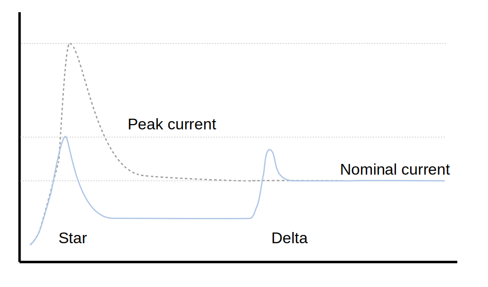 Star delta startup currents
A 100 kW motor has a nominal current of around 170 amp - that is under normal running conditions.
Using a DOL method, the startup current would be around 1250 amp (!!). Using a star-delta starter, the startup current is limited to about 1/3rd of that, or around 415 amp.
Typical setup of star-delta starter
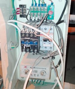
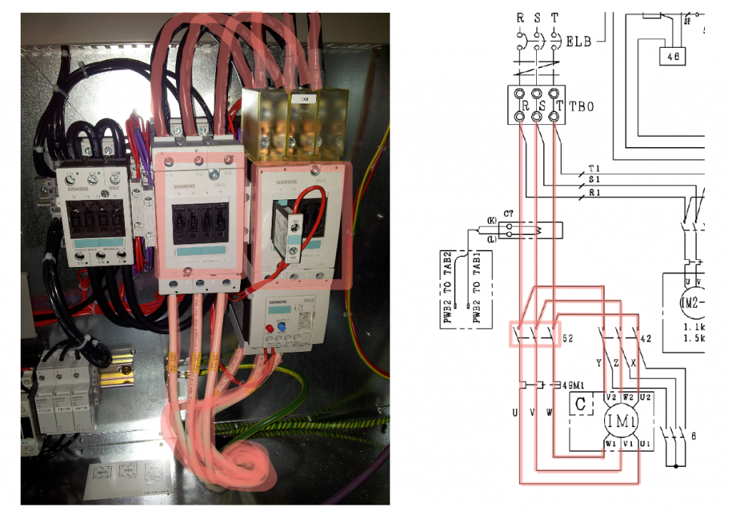
Here we see a typical setup of a star-delta starter:
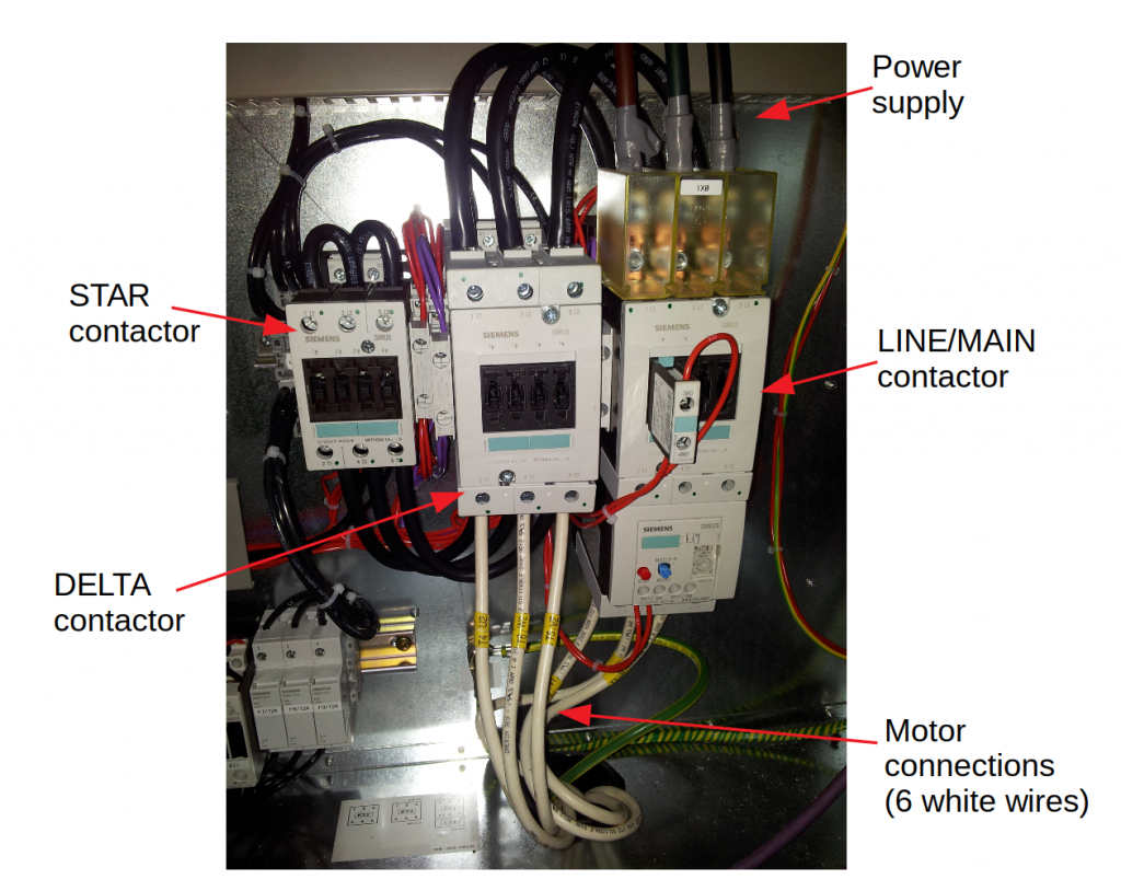 *Typical setup of a star-delta starter. There are 6 cables going to the motor (white, at the bottom)
Main contactors
The system always consists of 3 main contactors (big relais) in a typical configuration that is easy to recognize. The 3 contactors are:
- Main/line contactor
- Delta contactor
- Star contactor
Star
At startup, the main and the star contactor are energized. We can recognize the star contactor because on one side of it, all connections are connected together.
 Current flow in star
Delta
When switching from star to delta, the star contactor opens and the delta contactor closes.
 Current flow in delta
The time between start and the switch-over from star to delta is between 3 and 15 seconds - depending on the size of the compressor/motor.
The control system
To make the Y-D system work, we need a small control system - both for timing and performing the switch-over as well as assuring no short-circuit is possible. What should never-ever happen, is that the star and delta contactors close at the same time. This will essentially create a huge short-circuit - since we are actually simply connection the 3 phases together directly.
Auxiliary contacts and timer relay
To prevent this, every star-delta system has some extra contacts (a sort of miniature control system) to prevent this from ever happening.
These contacts are called the 'auxiliary contacts'. They open and close at the same time as the main contacts, but are completely separate. The auxiliary contacts are sometimes built-in into the contactor, but are often of the click-on type (you can 'click on' one or more auxiliary contacts to the main contactor).
By smartly positioning these auxiliary contacts in the path of of the control lines to the other contactor - we prevent them from closing at the same time - ever. The switching over is controlled by a timer relay. The timer is activated when the main contactor closes. After a set amount of time (seconds), the timer relay opens the star contactor and closes the delta contactor.
Air compressors with a central control unit sometimes have this timer and safety logic programmed into the controller - the auxiliary contacts are used as inputs to the central controller - so it can prevent short-circuits from happening and it can sense when something is wrong (for example a contactor does not close, when it should).
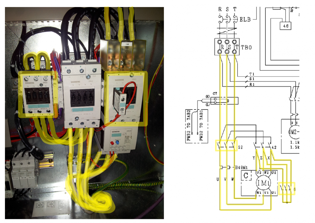
Here's a typical control system of a star-delta motor starter:
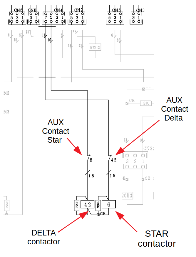 Auxiliary contacts in star-delta system
As you can see, when the star contactor is energized, the auxiliary contact opens (6-16) - this prevents the delta contactor closing at the same time (in case of a malfunction). The same is true for the star contactor - when the delta contactor is closed, auxiliary contact 42-15 opens, preventing the star contactor from closing.